I’ve been making better than status quo coffee tampers for several years now. The standard tamper design is largely driven by what’s cheap and easy to make on a lathe and not by what’s best for a barista. Rather than reinventing the wheel, I looked at traditional tools for tasks with similar biomechanics. Handsaws require a similar moderately forceful but controlled push along the axis of the forearm, so I based my design for a tamper handle on traditional handsaw totes, specifically dovetail saws which are a somewhat smaller type of handsaw.
At some point I may do a more complete write-up, but for now I want to put out enough info for other people to make these if they so choose, all associated design files are free to use under a creative commons license (Creative Commons Zero v1.0 Universal) unless otherwise specified.
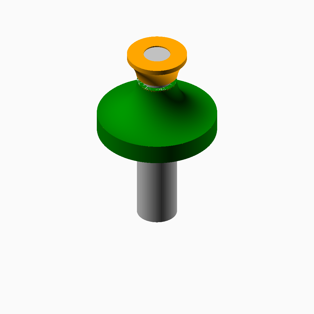
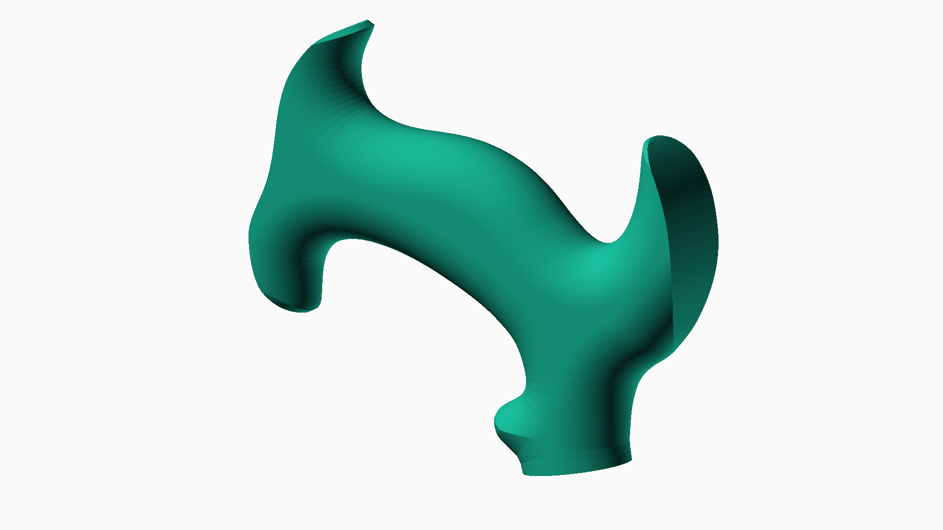
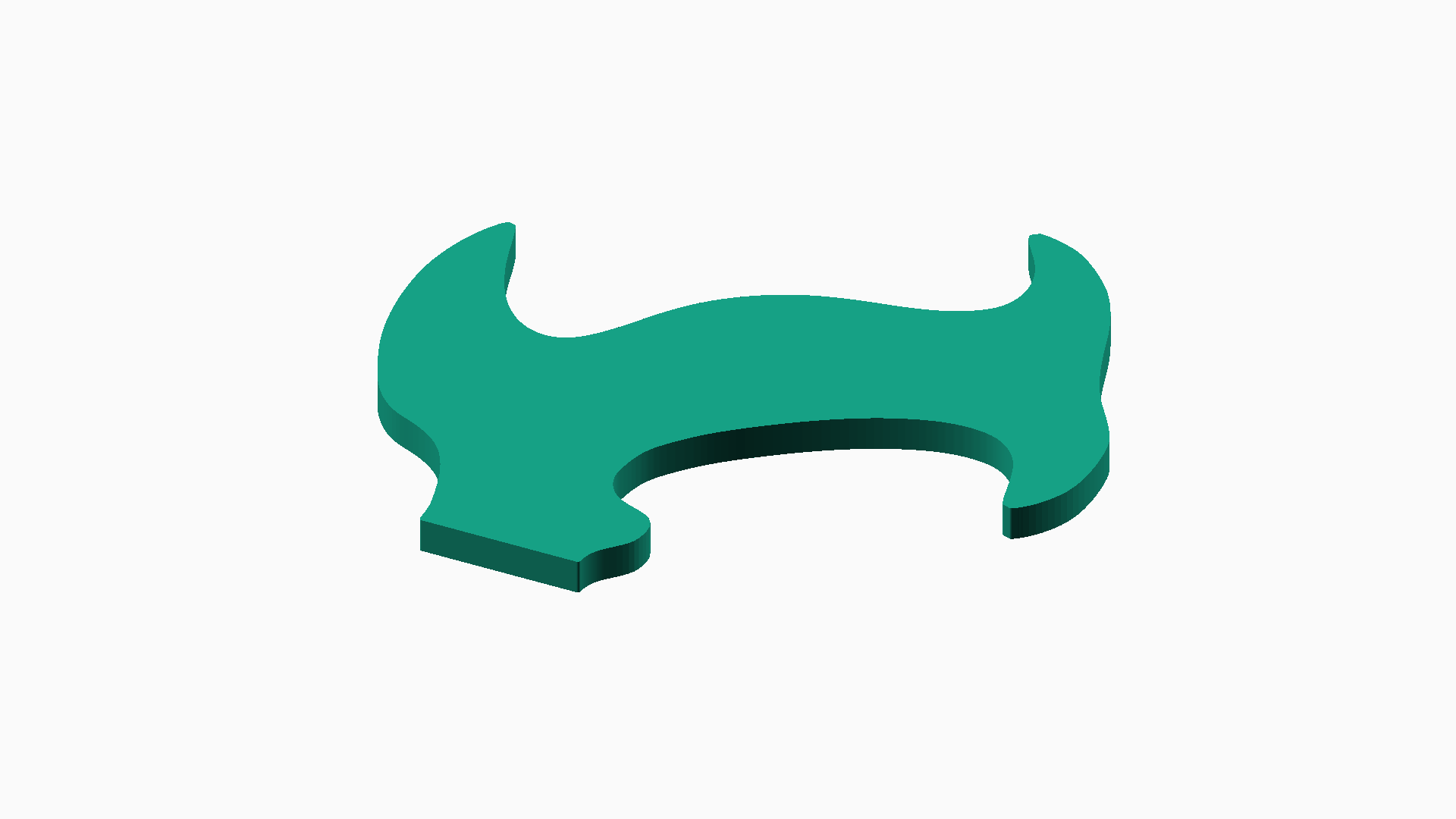
The defacto tamper base standard has a short 30mm diameter cylindrical pocket and a 3/8-16 threaded hole, a 3/8-16 set screw is then threaded into the handle to make a blind connection. Shown below are patterns for a slightly thinner 1“/25.4mm thick tamper handle. If used with a standard tamper base, you’ll need to add a small spacer to fill the cylindrical pocket. This spacer can be made separately; I print them in white ABS.
You can find STLs and openscad SCAD files here: https://github.com/TimPut/MechanicalThings/tree/main/tamper
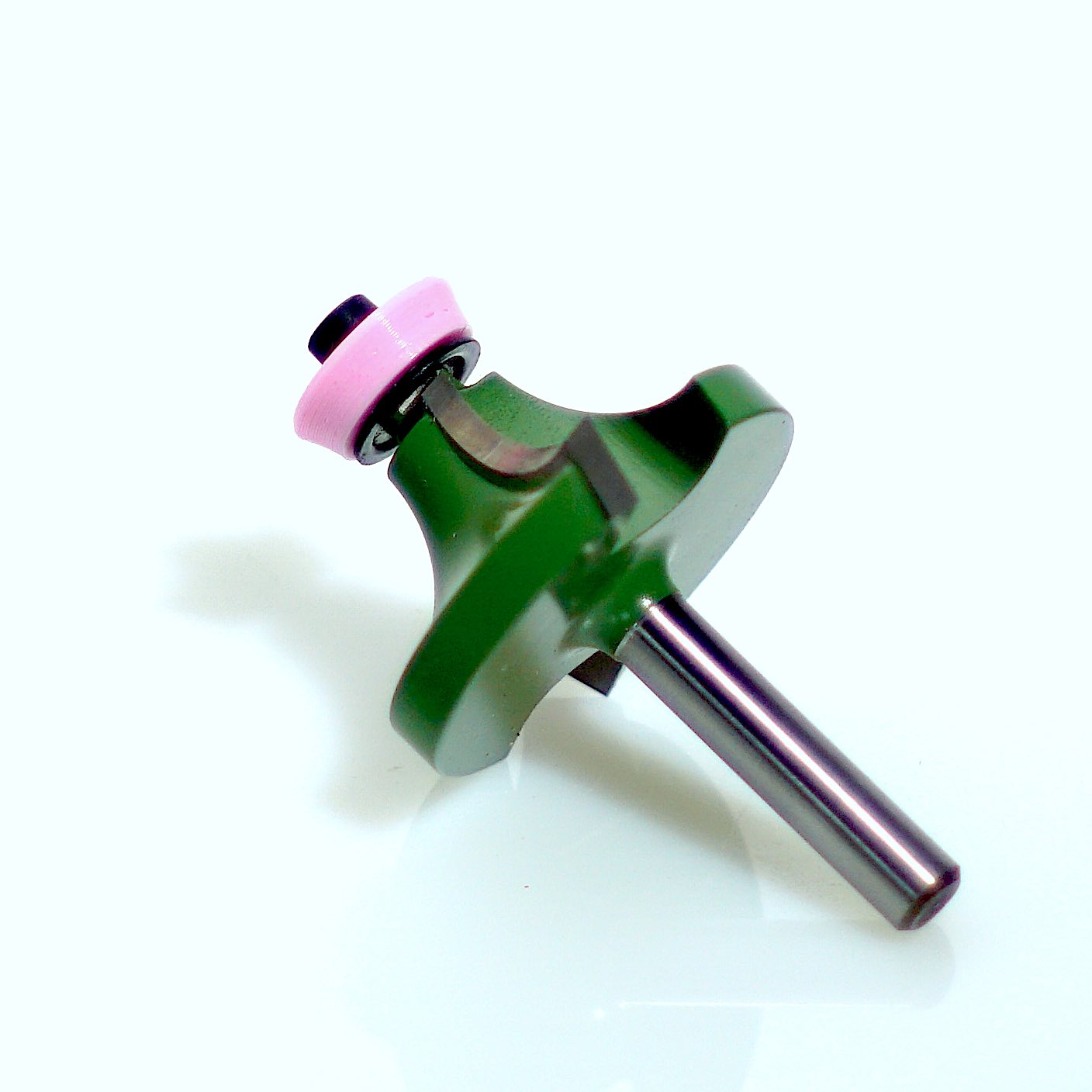
By making the tamper one inch thick, we can round over the edges with off the shelf router round over bits like this one from Lee Valley Item 16J2758, 1/2" Shank, 1/2" Radius Corner Round Over Bit. However, after we’ve rounded over the first side, when we go to round over the opposite side, there’s no flat area for the guide bearing to ride against and we can’t cut a full 180 degree round over. We can get around that problem by swapping out the bearing when we cut the second side. If we switch to a smaller bearing (in this case 3/8" diameter rather than 1/2" diameter, and sold as a beading bearing) and add a custom 3d printed bushing, we can ride on the previously routed edge and get a complete roundover. An STL for the bushing and the SCAD that generated can also be found at the github link above. Please note that when the bushing is not in contact with the workpiece, the bushing will spin at the same speed the router bit does and will experience strong centrifugal forces so make sure your layer adhesion is good and keep the major diameter of the bushing as small as possible for safety.